News
Inverter Driven Voltages, Part 2
Not too long ago VFD (Variable Frequency Drive) was making the news in the energy-savings arena, but VFD is only economically feasible on larger, commercial/industrial applications. Proving great energy savings on the commercial side couldn’t translate to the residential energy concerns simply due to the capital costs involved in the VF drive. The inverter drive is quite like the VFD, but different in that the motors controlled are essentially DC-powered electro-magnets driving permanent, shaft-mounted magnets (the present day ECM motor). The typical inverter drive system will convert AC voltage to DC voltage, which is then “gated” or switched in the IPM which alternates energy to the electro-magnets in the driven device (compressor).
 While most of the electrical consumed in a typical inverter driven air conditioning/heat pump system drives the compressor, other voltages become available once the Alternating Current is rectified to a DC voltage. Other components driven by DC voltage may include:
- EEV (12-15vdc)
- Condensing Fan Motor (310vdc)
- Thermistors (5vdc)
Each of these components are relatively easy to check and thermistors are no exception (EEV and condenser fan motor covered another day). Thermistors on indoor systems (wall hung boilers, communicating air handlers, mini-split indoor units) are not exposed to weather and so fail far less frequently than the outdoor thermistors. Outdoor thermistors however, are constantly exposed to the outdoor elements and therefore more likely to fail.
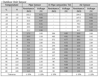
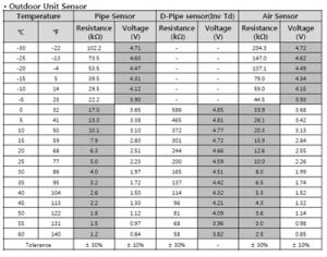
Most manufacturers provide a schedule of resistance values for the thermistors used in their product (with respect to this article, the reference is to DFS, or ductless mini split systems). When checking thermistors it is often recommended to remove the thermistor, provide a temperature constant (32F ice water) and diagnose the thermistor based on resistance (ohm) values. However, since the converter produces DC voltage not only to the IPM, but indeed to other component, instead of removing the thermistor we can check in place, measuring the DC voltage across the thermistor with power on.
Not all manufacturers provide a DC-voltage chart as shown below (courtesy LG Electronics), most will provide only the resistance chart, but if available the faster, easier way to check thermistors is live and in place. Knowing the DC voltages that should be present on a PCB allows checks of components in place.
Dan Applegate is a DFS/VRF National Trainer and a Senior Product Specialist.