News
Inverter Driven – Voltages, Part 1
Diagnosing inverter drive systems in many cases is easier than diagnosing electro-mechanical/analog systems. The inverter drive will report error codes both external to the device (temperatures at compressor discharge, evaporator, etc) and internal faults (IPM, EEPROM) but the error cause may be ambiguous. An IPM failure could mean more than simply an IPM (inverter power module) failure; it could be that the converter has failed or that one or more IGBTs (switching transistors) have failed.
The inverter drive consists two parts: converter and inverter. The inverter forms and controls the 3-phase sine wave to the compressor, but it must receive the proper input voltage to function. That input voltage is derived from the converter. An input of 240vac is rectified, or converted, to four distinctly purposed voltages. Any diagnosis begins with determining whether those voltages are present and in the correct quantity.
The converter produces voltages:
- The inverter receives 310vdc, which is then “gated” or switched through the IGBT to power the compressor
- 15vdc is produced for the condensing fan motor
- 13vdc powers the EEV, or “stepper motor”
- 5vdc powers the CPU (central processor) and provides signal voltage between the IPM and PCB. Thermistors also use 5vdc as a reference voltage.
In the diagram below, the voltage produced by the IPM is 310vdc. Some manufacturers produce a diagnostic tool which can source that voltage; other manufacturers allow a DC voltage check at the IPM in other ways. Few provide other means of voltage checking at this reference point other than scratching away the enamel coating to access with needle probes. Doing so requires a re-coating of the test areas with a spray enamel for weather protection, so if an inverter manufacturer provides a diagnostic tool and you intend to reqularly sell that brand product, a diagnostic tool is a good investment.
 Whether by convenient diagnostic tool, or “old school” scratch and test, the converter must be proven to provide the proper voltages to the IPM and PCB. If the converter fails to function properly, error codes will be reported in other areas. Proper converter function follows this equation:
Incoming voltage: 220 x 1.414 (the squre root of 2) = 310vdc, as is described in the above diagram.
However, as incoming voltage varies so too does the DC product. The 220v sourced here is common to the Asian continent (220/50Hz), whereas in the continental U.S. we see 230/60Hz, with deviations on that voltage as much as 10% (207-257). Therefore, when determining input voltage to the IPM, incoming line voltage to the converter must be considered, such that:
230vac x 1.414 = 325vdc.
240vac would yield a 339vdc product, and so on. As the incoming line voltage varies, so too does the net DC voltage product.
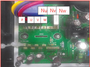 This photo shows the 3-phase legs: red, yellow, blue, going to the compressor. Those legs come from the IPM, which has a negative (N) and positive (P) output. Test each leg between P and N to determine the voltage produced by the converter. A failed converter will result in an IPM fault code.
Dan Applegate is a DFS/VRF National Trainer and a Senior Product Specialist.