By Jon LaPorta, Pfannenberg USA
Variable frequency drives are a hot topic. Advancements in VFD technology and reductions in price
are driving rapid market adoption. Dramatic energy savings can deliver a payback period measured
in months, and VFDs enable precise motor control in many industrial process applications.
But VFDs are also hot in the literal sense: the advanced electronics pack more semiconductor
components into a smaller form factor resulting in more intense heat generation. Elevated
temperatures degrade performance, impair operational reliability and shorten service life.
A variety of cooling methods have proven effective, including passive air cooling with fans and heat
exchangers, and active cooling with air conditioning and water cooling.
Unfortunately, determining the cooling load can be a bit confusing. Calculations are needlessly
complicated by a mismatch of systems of measurement. — Imperial units (HP, BTU, CFM) mixed
with Metric units (Watt) — and the conversion gets lost in translation.
Therefore, at Pfannenberg we have developed simple rule-of-thumb guides for selecting and sizing
VFD cooling solutions.

Protective enclosures cause overheating
The basic challenge of VFD cooling comes from the fact that VFDs usually need to be placed in an
enclosure to protect them from the immediate environment, and paradoxically, these enclosures
trap heat which necessitates protection from overheating.
Basic NEMA 12 type enclosures are often specified to protect against common hazards such as
settling dust, dripping water and condensation of non-corrosive liquids. Increasingly, advanced
technologies in new VFDs such as fiber optics require enclosures with more enhanced levels of
protection.
And with the wide scale adoption of VFD technology, many applications require enclosures specially
designed for challenging environments, from weather and impact resistant outdoor enclosures to
tightly-sealed stainless steel enclosures for food production facilities that must withstand hosedown
cleaning. As an enclosure becomes more sealed it naturally starts to hold in more heat, due to the
decrease in passive dissipation, thus creating a larger cooling challenge.
The size of the enclosure also matters a great deal. Typical enclosure dimensions have been
dramatically scaled down in recent years, to fit in tighter spaces and to economize on the cost of the
enclosure. In a large box — imagine a space the size of a room — the difference in temperature between
the floor area and the ceiling area causes a slight airflow called natural convection. The
smaller the space, the less objects are able to benefit from this cooling effect. Without adequate
airflow, a phenomenon known as “hot spots” is more likely to develop on the surface and in the
interior of VFDs, wreaking havoc on sensitive electronics.
The smaller form factor of VFDs and their enclosures contribute to overheating in another way: a
smaller box means that less surface area on the exterior is available to transmit heat to the
surrounding air. All of these factors necessitate effective and reliable cooling solutions.
Rapid Adoption of VFDs
But first, let’s step back from the box and consider the big picture. The energy efficiency of VFDs is
not just good for individual businesses, it is also key to addressing climate change.
Worldwide, about a quarter of all electrical energy is used to supply motors in industrial
applications. In the U.S., an estimated 40 million motors consume 60-65% of all electrical energy.
Three quarters of these motors are variable-torque fan, pump and compressor loads, the types of
applications ripe for the energy efficiency afforded by VFDs.
Today, only about 3% of AC motors are currently controlled by VFDs, but about 30-40% of new
motors installed each year have a VFD. According to a 2021 report by Research Dive, the global
variable frequency drive market is estimated to grow at nearly 5% annually to $25 billion in 2027.
The energy savings are dramatic. VFDs reduce energy consumption by enabling electric motors to
operate at less than full speed. Basic AC induction motors are designed to run at a constant speed,
but in actual use, speed requirements fluctuate, with full speed typically employed only about 10%
of the time. The inherent inefficiency is obvious, analogous to running a car engine with the
tachometer showing the engine constantly at its maximum speed.
The energy savings can be calculated using the Laws of Affinity: the electrical power drawn is
proportional to the cube of the rotational speed. Therefore, slowing a pump or fan to 75% speed
reduces energy consumption by nearly 60%, and 50% speed saves almost 90%.
From these efficiency gains, it is necessary to subtract the relatively minimal energy waste of about
3% due to heat loss from the VFD. This heat loss from the VFD is important to quantify, not for its
financial impact, which is minimal compared to the overall efficiency gains of utilizing the
technology, but rather for the danger that overheating poses to the VFD electronics if the heat
trapped in the enclosure is allowed to exceed acceptable temperature limits.
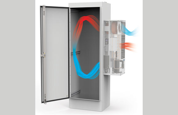
When to choose passive cooling and when to choose active
There are two different types of cooling, the first being passive cooling and the second being active
cooling, both types utilize The Second Law of Thermodynamics which in simple terms is that energy
goes from a higher source to a lower source. Passive cooling utilizes the natural path of heat transfer
with the heat going from the higher temperature source to the lower temperature source. A good
example of this is filterfans, filterfans move the colder ambient air into and through an enclosure
where that air absorbs heat until it is exhausted and the heat dissipates into the environment.
Active cooling requires a source of energy to be put into the system in order to create a path for heat
to transfer. This is commonly done with the use of a vapor compression cycle, a vapor compression
cycle has four major parts, a compressor, a condenser, a throttling device, and an evaporator. The
cycle starts with the compressor where energy is put into the system, refrigerant enters the
compressor under low pressure and low temperature where it is compressed which causes the
refrigerant to leave the compressor under high pressure and high temperature. Next the refrigerant
travels through the condenser where heat is removed causing the refrigerant to become a saturated
or subcooled liquid. Then the refrigerant passes through a throttling device where its pressure and
temperature drop. Finally, the refrigerant passes through the evaporator where heat is absorbed
turning it into lower pressure and low temperature gas, where the cycle can then repeat.
Deciding when to use passive and when to use active is fairly simple. If your ambient temperature is
lower than your target enclosure temperature or you have a source of passively chilled water, then a
passive cooling unit can be used which is desirable for energy savings. Passive cooling uses
significantly less energy than active cooling, as the passive cooling does not require energy to be put
into the system to allow a path for heat transfer. If your ambient temperature is higher than your
target enclosure temperature or you do not have a source of passively chilled water, then an active
unit has to be used.
Simple way to calculate cooling requirements
Here is a simple way to calculate cooling requirements for both active cooling and passive cooling
methods.
Active Cooling Rule of Thumb
VFDs are typically sized in horsepower (HP) and cooling systems are measured in British Thermal
Units (BTU, or BTU/h for BTU hours). But how do you convert from HP to BTU/h?
Here is the rule of thumb for air condition and water cooling:
75 BTU/h is required for every 1 HP
In other words, for a 100 HP VFD drive, 7500 BTU/h of cooling is required.
This rule of thumb is derived as follows:
● 3% of the electrical energy in a VFD is converted to heat
● 1 HP = 746 watts
● 746 watts x 3% heat loss = 22 watts of heat loss per 1 HP
● 1 watt = 3.4 Btu/h
● 22 watts x 3.4 BTU/h = 75 BTU/h per 1 HP
Passive Cooling Rule of Thumb
For passive cooling solutions, such as the Pfannenberg Datawind Filterfan®, the rule of thumb is
4 CFM is required for every 1 HP to maintain 10°C above ambient in the enclosure
In other words, for a 100 HP drive, 100 CFM is required.
This rule of thumb is derived from the following equation
1 CFM = 1.82 x watts of heat loss / Δ Temp (°C)
These rule of thumb guides provide a general guide for selecting a cooling method and for sizing the
cooling load requirements. For more precise calculations that account for ambient temperature and
humidity and other critical considerations, we provide Pfannenberg Sizing Software at no charge.
By simplifying the calculation of cooling requirements, we hope that the adoption of VFD
technology will continue to grow rapidly, and that users will benefit from maximum performance
and service life.