News, Refrigerants, Technology, Trends
Demystifying CO2 Refrigeration
An introduction to the characteristics, nuances and applications of an emerging natural refrigerant
By Andre Patenaude, Director, Solutions Strategy, Emerson
The use of CO2 as a refrigerant (R-744) in commercial refrigeration is expected to rise significantly in the U.S. over the next several years. With a global warming potential (GWP) of 1 and zero ozone depletion potential (ODP), CO2 is one of several emerging refrigerants capable of enabling food retailers to meet their sustainability goals and comply with environmental regulations.
 Although CO2 refrigeration has been a known commodity on the world stage for many decades, many supermarket owners, operators and service technicians in the U.S. have had very little (if any) exposure to it. The characteristics of CO2 refrigeration are quite different from traditional hydrofluorocarbon (HFC)-based systems, which has created reservations about applying it within U.S. food retail outlets.
Today, as U.S. food retail stakeholders transition away from high-GWP HFC systems, they have many questions about emerging CO2 refrigeration technologies. This article, combined with our CO2 Chats video series, is designed to demystify CO2 refrigeration and provide the basic information needed to help establish a foundational understanding.
Unique properties of R-744
Compared to legacy HFC refrigerants, R-744 has a multitude of distinct thermo-physical properties and performance characteristics.
Low critical point
Among its many distinguishing characteristics, R-744 has a low critical point of 87.8 °F — which from a refrigeration perspective, is a relatively low temperature. When the ambient (outside) temperature rises above approximately 75 °F, system conditions cause the refrigerant to enter the gas cooler as a supercritical fluid (at or above 87.8 °F), where its pressure and temperature relationships can rise and fall independently of each other. R-744 is at saturation when it is below the critical point, which is referred to as subcritical mode; above 87.8 °F, the refrigerant transitions to transcritical mode.
High operating pressures
CO2 system operating pressures are significantly higher than traditional HFC systems (i.e., those using R-404A or R-410A). Although this often gives service technicians pause when they first encounter CO2 transcritical booster systems, understanding where those pressures occur can give them a greater comfort level. As medium-temperature (MT) compressors discharge into a gas cooler on the roof, pressures could reach 1,400 psi on a 95 °F summer day. MT discharge lines are constructed with stainless steel or special ferrous alloy copper to handle these pressures.
Within a facility and/or machine room, a high-pressure expansion valve reduces the refrigerant pressure exiting the gas cooler to around 550 psi and transfers it to a receiver tank, commonly referred to as a flash tank. Liquid refrigerant exits at the bottom of the flash tank via a main liquid line at 40 °F (550 psi) and feeds all the MT evaporators, which operate at about 22 °F (420 psi). It also feeds all the low-temperature (LT) evaporators, which operate near -20 °F, at an even lower pressure of 200 psi. Although system pressures are higher than what most technicians are accustomed to, proper training and tools should mitigate the reservations of CO2’s high pressures.
High triple point
R-744 has a high triple point at which the refrigerant’s gas, liquid and solid states coexist — occurring at
-69.8 °F and 60.4 psi. Although -69.8 °F is well below normal operating ranges, its corresponding saturation pressure is not 60.4 psi. The hyper-reactivity of a CO2 system can cause the pressure to reach 60.4 psi or lower. When this occurs due to improper maintenance, R-744 turns into dry ice, stops the refrigerant flow, and causes a variety of potential problems.
High density
R-744 has other unique performance and operating characteristics that dictate system design strategies. Because it has a higher density than typical HFC refrigerants, CO2 requires the use of smaller compressor displacements — although the motor is sized similarly to carry the workload. CO2’s higher density means that smaller pipe diameters can be used, especially on the suction side of the system. Due to its high pressures, system components must be rated for a higher maximum working pressure.
Servicing best practices
CO2 transcritical booster system installations are expected to increase significantly in the next few years. It’s only a matter of time before technicians will be asked to perform service on them. Technicians should be aware of the following basic best practices when servicing these systems.
Storing CO2
R-744 tank storage and/or refrigerant cylinder best practices are similar to those of legacy HFCs, including stacking procedures, safety precautions and assigning designated storage areas. To handle its high pressures, CO2 tanks are reinforced and weigh significantly more than HFC tanks. Empty CO2 tanks can weigh close to 123 lbs. and can reach nearly 180 lbs. when fully charged. Supermarkets that prefer to have an entire system charge in reserve could potentially require 2,000 lbs. of refrigerant. Storing that amount would require 40 cylinders weighing 7,200 lbs. — or 3.6 tons. Contractors need to understand where to store the reserve refrigerant and if the sheer volume and weight could affect building codes and/or a building’s structural integrity.
Charging a CO2 refrigeration system
When charging a CO2 refrigeration system, the most important consideration a technician should keep in mind is the refrigerant’s triple point pressure (60.4 psi) and how to guard against turning the charge to dry ice. Instead of charging with liquid CO2 when the system is below 60.4 psi, contractors should charge with vapor until the system reaches CO2’s triple point. Failure to do so is likely to result in the formation of dry ice in the charging line, a common (and potentially costly) mistake for those unfamiliar with CO2 installations. Most equipment manufacturers recommend charging the system with vapor until it reaches at least 100 psi. After achieving 100 psi with vapor, which has equalized throughout the entire system, technicians can switch charging with liquid to speed up the process.
Dealing with trapped liquid
Because CO2’s coefficient of expansion (COE) is higher than a typical HFC refrigerant, it has a higher probability of refrigerant pressure increasing rapidly between two valves. If this occurs, the pressure can increase 145 psi for every 1.8 °F increase in temperature. As a result, sections of a system need to be fitted with appropriate check valves or pressure-relief valves for safe system operation and service.
Detecting leaks in CO2 systems
Because R-744 refrigerant is colorless, odorless and heavier than air, it can be difficult for building occupants to detect leaks. CO2 transcritical booster systems must utilize integrated leak detection systems with detection devices mounted 18 inches off the ground. Like HFC systems, it’s important to immediately detect and mitigate CO2 leaks as they occur.
Emerson has designed CO2-specific leak detection technology that quickly can sense the presence of higher levels of CO2 in a machine room or walk-in box. Emerson offers both a stand-alone CO2 leak detection solution as well as devices that can be seamlessly integrated into a building management system (BMS), such as the Lumity™ supervisory control platform.
Safe handling best practices
Technicians should take proper precautions when handling high-pressure CO2 refrigeration systems. Even when a system is shut off, standstill pressures are still likely to remain high and should be handled accordingly. Because it is heavier than air, CO2 can quickly displace O2 when it is released in excessive amounts. Thus, technicians should avoid handling it in confined spaces and ensure they use proper leak detection procedures and equipment. In addition, CO2 vapor temperature at atmospheric pressure is -109.3 °F; technicians should follow proper service procedures and always wear personal protective equipment (PPE) to limit the potential for skin burns. With proper training, tools and equipment design — and when maintained and operated properly — CO2 is a safe and natural refrigerant alternative.
Fundamentals of CO2 system operation
Because of R-744’s many distinguishing performance characteristics, CO2 transcritical booster system design can seem more complex to operate and service. Fortunately, system control technologies have evolved to manage nearly all aspects of operation and make it easy for operators to manage these complexities. Even so, end users and contractors should be aware of the basic principles when operating CO2 transcritical booster systems.
The difference between subcritical and transcritical modes
CO2 transcritical booster systems are designed to transition between subcritical and transcritical modes of operation. When R-744 is at saturation and below the critical point of 87.8 °F, a system operates in subcritical mode. Above this refrigerant temperature, R-744 is no longer at saturation and the system enters transcritical mode. Unlike traditional HFC systems that have much higher critical points, CO2 systems could operate for extended periods while in a transcritical mode in a typical year.
Managing high system pressures
R-744 is a very dynamic refrigerant that reacts quickly to changes in pressures and temperatures. During the commissioning of a CO2 transcritical booster system, it’s important to establish a stable baseline of performance. To achieve this, technicians should focus their efforts on the configurations of the gas cooler, high-pressure valve and flash tank, including:
– Controlling variable fan speeds
– Modulating the high-pressure valve
– Modulating the bypass gas valve
– Maintaining a consistent flash tank pressure
– Assuring smooth compressor staging
Since all those aspects are managed by electronic controls, technicians will need to interface with these controls to bring the key system components into equilibrium.
Preserving CO2 system charge during a shutdown
Power outages and system shutdowns can have significant impacts on a CO2 transcritical booster system. In the event of an extended shutdown, CO2 transcritical booster systems are designed with pressure-relief valves in each zone to allow for the safe release of refrigerant. During brief shutdowns, system pressures typically don’t rise quickly enough to cause concern. A system’s existing thermal inertia — from its flash tank, liquid line, MT and LT evaporators — will sustain proper pressures for a significant period of time. The temperatures outside and inside the building, among other factors, are likely to impact how long pressure will be sustained.
Another method for keeping pressures in check and preventing the release of system charge during an extended power outage is through an auxiliary condensing unit powered by a backup generator. The condensing unit typically utilizes a dedicated heat exchanger connected to the system’s flash tank or receiver. When the system is powered down, warm gas from the receiver naturally migrates through the cold heat exchanger, cools the flash tank vapor, condenses it into a liquid, and returns it to the flash tank at a colder temperature and lower saturation pressure. This helps to prevent the loss of refrigerant through pressure-relief valves.
Preventing flooded evaporators during a power outage
CO2 transcritical booster systems are designed with specific strategies to prevent CO2 evaporators from flooding during a power outage. When the power drops in a system using a stepper-motor electronic expansion valve (EEV), the EEV typically will hold its exact position. Accordingly, CO2 transcritical booster systems are often designed to have a solenoid valve at the inlet of the EEV, which can be set to close upon losing power to help prevent flooding of the evaporator. Another strategy that would work is to install a battery backup on the case control to shut off refrigerant flow when necessary.
Systems equipped with pulse-width modulated (PWM) valves — which are in effect high cycle rate solenoid valves — are designed to automatically close to prevent liquid from flooding the evaporator, thereby protecting the compressor when power comes back on. Before the system is up and running again, service contractors should make sure that they clearly understand how the valves in each system will operate and/or close — and to confirm that any floodback mitigation strategies have worked as expected.
Leading CO2 system design strategies
Refrigeration system designers have made tremendous strides in exploiting CO2’s unique properties into sustainable refrigeration architectures. Today, system design strategies have evolved into two primary architectures that differ greatly from traditional HFC-based systems.
CO2 transcritical booster system
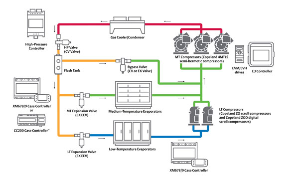
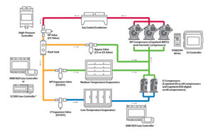
CO2 transcritical booster systems are designed so that MT compressors discharge into a gas cooler, typically located on the roof of a facility. With system pressures potentially reaching 1,400 psi on a hot summer day, R-744 must be cooled before it can be condensed. Thus, refrigerant is circulated back into the building through a high-pressure valve, which drops the pressure to a useable state (550 psi) and deposits a refrigerant mixture of vapor and liquid inside the flash tank at 40 °F equivalent saturation.
Next, the system circulates the 40 °F liquid through insulated liquid lines to feed all the MT and LT cases and provide the cooling loads. The MT cases are equipped with an EEV, and the MT suction gas feeds the MT compressors. On the LT side where loads could be -20 °F, the cases are also fitted with an EEV and are supported by a separate set of LT compressors that discharge into the MT suction group.
The system also utilizes a bypass line that’s designed to relieve the pressure on the flash tank. As ambient temperatures rise and fall, flash tank pressures can also fluctuate. Thus, the bypass line helps to release the excess flash tank pressure through a bypass gas valve and stabilize it to approximately 550 psi (pressure may vary based on system design), where it is directed into the MT suction group. In effect, the MT compressors are being fed by three sources:
– The total heat of rejection from the LT compressors
– The MT suction from the evaporators
– The excess flash gas via the bypass line
The system is called a booster system because the LT compressors are not going directly to the gas cooler, like they would on a typical HFC system. Instead, the LT compressors discharge into the MT compressors, thereby allowing the MT compressors to boost the refrigerant to the gas cooler.
CO2 cascade system
A CO2 cascade system offers an alternate architecture for retailers who want to deploy a low-GWP option but may not want a full CO2 transcritical booster system. In a CO2 cascade system, the high (MT) and low (LT) stages are completely independent of each other, except for one heat exchanger that connects them.
Typically, the high stage of a supermarket system would use a lower-GWP, medium-pressure HFC refrigerant, such as R-513A. Not only does it serve the MT loads, but it is also used to condense the CO2 in the low stage. In the low stage, CO2 is discharged, condensed in a condenser, and then recirculated for LT loads. R-744 is a very effective refrigerant for LT loads; and with a GWP of 1, it contributes to a cascade architecture that could meet many retailers’ sustainability objectives.
Leveraging heat reclaim
CO2 systems are excellent candidates for heat reclamation strategies. In fact, most modern CO2 systems utilize some form of heat reclamation — whether it’s for providing heated air, hot water, or even heating slabs beneath freezers. Many retailers are capitalizing on this opportunity to lower their emissions and reliance on fossil fuels. In addition, the liquid quality of R-744 is not affected when head pressures are raised to generate more heating capacity. Instead, the flash tank or receiver is designed to keep refrigerant at a consistent pressure, even while head pressures may fluctuate while operating in transcritical mode.
Optimizing the COP via the high-pressure control
When R-744 exceeds its critical point of 87.8 °F, the refrigerant enters a supercritical phase where the relationship between pressure and temperature becomes uncoupled. To optimize the coefficient of performance (COP) in a CO2 transcritical booster system, we must understand the function of the gas cooler and the characteristics of R-744 as it enters this supercritical zone.
Below the critical point, the gas cooler acts like a condenser. Thus, R-744 exists in a predictable state of saturation — if you know the pressure, you can determine the temperature (and vice versa). In its subcritical state, the high-pressure control algorithm automates system pressures according to a specified sub-cooling setpoint.
Above 87.8 °F, the pressure can change without having an impact on the temperature (and vice versa). System designers can take advantage of this phenomenon when optimizing COP. When operating transcritical mode, the high-pressure control always seeks to maintain an optimal pressure setting for each gas cooler outlet temperature. Today’s sophisticated high-pressure controls are continually adjusting gas cooler outlet pressures in transcritical mode to produce the most optimal BTU/W option.
Maintaining energy efficiencies in warm climates
The energy consumption of a refrigeration system is a key factor when evaluating its total cost of ownership (TCO). For a CO2 transcritical booster system, energy efficiency is dependent on many factors, including:
– The ambient temperature range
– The humidity of the region
– The availability of and cost of water
– The cost of peak demand charges
Among these factors, the goal of improving system energy efficiencies in warmer climates has become a major focus area for equipment manufacturers. Leading system design optimization strategies typically include:
– Adiabatic gas cooler
– Parallel compression
– Mechanical sub-cooling
– Gas ejector
– Zero superheat control of MT evaporators (annualized benefit)
– Liquid ejector (annualized benefit)
Retailers must consider all these variables and strategies when they work with their equipment suppliers and design engineers to specify a CO2 transcritical booster system.
Adiabatic gas cooler
An adiabatic gas cooler utilizes wetted pre-cooling pads outside the condenser coils to delay a CO2 transcritical booster system from entering into transcritical mode. When the ambient temperature reaches about 72 °F, a water solenoid valve is energized, causing water to be sprayed along the top of the adiabatic pads. As the water trickles down the pads, a condenser pulls air through these wetted pads, causing moist, cooler air to hit the coils. In turn, the condenser reacts to this cooler air and drops the temperature and pressure, making the system significantly more energy-efficient by operating at lower pressures.
Parallel compression
In a CO2 transcritical booster system, parallel compression refers to the practice of adding a separate suction group that is “parallel” to the existing MT suction. Thus, instead of the bypass gas circulating from the flash tank to the MT suction as in a standard transcritical booster system, the parallel compressor suction group compresses excess flash gas and circulates it directly to the gas cooler.
This allows the parallel compressor to operate at a suction pressure of about 550 psi (the same as the flash tank), instead of the MT suction of 420 psi. The net effect of leveraging the higher suction pressure is achieving higher compressor capacity for less effort, which translates into a lower heat of compression and reduced energy consumption. Parallel compression is considered a foundational high ambient strategy with which other energy mitigation methods can be used in combination. When annualized in a typical environment, it can potentially save up to 10% in energy costs.
To learn more about the topics discussed herein, please view the companion installments in our CO2 Chats video series. For more information about Emerson’s comprehensive CO2 products and capabilities, please visit Climate.Emerson.com/CO2Solutions.
Andre is responsible for supporting system-related innovation and leveraging Emerson’s global cold chain to drive adoption of integrated solutions in North America. He most recently led marketing efforts pertaining to Emerson’s food retail and chiller markets. Prior to that, he had managed Emerson’s global CO2 development.
Andre has more than 35 years of industry experience in sales, marketing, training and business development of HVACR system architectures and applications with compression and component technologies. He is a certified Mechanical Engineering Technologist C.E.T. (since 1984), and is a member of AHRI, ASHRAE and RSES.

